Strategy ONE
Using Connectors to Create the Logical Order of a Workflow
When a process in a workflow is completed, the next step to take in a workflow is determined using connectors. Connectors determine the logical order of a workflow according to the exit code of the process they are coming from. You can select from the following types of connectors:

- Success: The green arrow, to the left, is the success connector. If a process is completed with an exit code that is defined as a successful status, the process that the success connector points to is the next process that is attempted. If you use a success connector from a process, it is recommended that you also provide a failure connector. Without a failure connector, the workflow may unexpectedly end with the current process.
- Failure: The red arrow, in the middle, is the failure connector. If a process is completed with an exit code that is defined as a failure status, the process that the failure connector points to is the next process that is attempted. If you use a failure connector from a process, it is recommended that you also provide a success connector. Without a success connector, the workflow may unexpectedly end with the current process.
- Continue: The white arrow, to the right, is the continue connector. Regardless of the status of the exit code for a process, the process that the continue connector points to is the next process that is attempted. If you use the continue connector from a process, you cannot use any other connectors for that process.
When a connector is added to a workflow, it is drawn from one process to another. The arrow for the connector points to the next process to attempt in a workflow, and the start of the connector links to the process that was just completed.
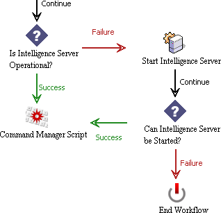
It is common to use a combination of success and failure connectors to lead from a process. These connectors allow you to continue with the main workflow if the process was successful, and end the workflow or troubleshoot the problem if the process was unsuccessful. For example, the steps of a workflow shown in the image below show success and failure connectors leading from a decision process.

The first decision process shown in the image above determines if Intelligence Server is operational. If so, the workflow follows the success connector to continue on to a Command Manager script to perform various configurations. If Intelligence Server is not operational, the workflow follows the failure connector on an alternative path to attempt to start Intelligence Server before attempting the Command Manager script.
This example also includes a few continue connectors. For example, the Start Intelligence Server process uses a continue connector to lead to a decision process. The decision process is then used to determine the exit code of the previous process. For examples of how decisions can be used to define the logical order of a workflow, see Using Decisions to Determine the Next Step in a Workflow.
