Strategy ONE
Structure of a Layout Definition File
The layout definition file is structured as a plain text XML file which must adhere to the XML structure defined in the MicroStrategy layout document type definition file mstrlayout.dtd (located under WEB-INF/xml/dtds in the MicroStrategy installation directory). This type definition is an extension of the W3C XHTML definition version 1.1 that includes MicroStrategy Web-specific elements capable of including dynamic MicroStrategy content. By default, the layout definition is validated against a local version of the XHTML11 dtd, xhtml11-flat.dtd (located under WEB-INF/xml/dtds in the MicroStrategy installation directory). All layout definition elements are given the prefix of mstrlayout:— as in, <mstrlayout:render .../> or <mstrlayout:include .../>. For information about the W3C XHTM definition version 1.1, visit http://www.w3.org/TR/xhtml11.
If the default document type definition is used, the layout document has the following basic structure:
<!DOCTYPE mstrlayout:layout SYSTEM "mstrlayout.dtd">
<mstrlayout:layout>
</mstrlayout:layout>
To ensure compliance with W3C XHTML definition version 1.1, you should use an XML editor to edit the layout definition files so they are validated as you make modifications. In order to have an XML editor validate your layout files, copy the following DTD files to the same folder as the layout definition files:
-
xhtml11-flat.dtd
-
mstrlayout.dtd.
Structure of the content in a layout definition file
To understand the structure of the content in a layout definition file and how it is used with a transform to render content, consider a layout definition that presents a simplified version of the folder browser. This simplified version uses the same folder browsing transform Java class as the typical folder browser presentation, but the folder contents are displayed as a simple bulleted list as shown below. The output displays the name of the current folder, with the folder contents represented as icons and object names listed beneath the name.
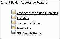
To present the data as shown above requires the creation of an HTML structure similar to the HTML code shown below. The portions of the code indicated in colored italics denote dynamic content that is retrieved from the bean using the transform.
<p>
<br>
Current folder:Reports by Feature
<br>
</p>
<tableclass="listView" cellspacing="0" id="FolderList">
<tr>
<td><img src="foldericon.gif" /> Advanced Report Examples<br>
<img src="foldericon.gif" /> Analytics
</td>
</tr>
</table>
Referring to the code sample above, you can see that a way is needed to dynamically obtain the name of the folder (in this example, Reports by Feature), the icon for the object (in this example, foldericon.gif), and the name of the object (in this example, Advanced Report Examples, Analytics, and so on) and insert them into the HTML code for creating the list of folder contents. This can be accomplished by creating a layout definition file, which is a combination of static HTML as well as instructions to render dynamic content such as the folder or object name at certain locations within the HTML.
A generic version of the HTML responsible for displaying the folder contents is shown below. The specific values shown in colored italics in the code sample above are replaced by text that indicates the content that needs to be created dynamically. This dynamic content is obtained and inserted after the contents of the folder are retrieved from the metadata.
<p>
<br>
Current folder:{insert folder name here}
<br>
</p>
<tableclass="listView" cellspacing="0" id="FolderList">
<tr>
<td>{insert icon for the first object here} {insert name of first object here}
{insert icon for the second object here}nbsp;{insert name of second object here}
</td>
</tr>
</table>
To obtain the dynamic information that needs to be inserted into the static HTML contents, the HTML code needs to include a series of instructions that the MicroStrategy Web application understands. These instructions are provided by a series of MicroStrategy custom tags— primarily the <mstrlayout:render> tag with its child <mstrlayout:argument> tags, but also the <mstrlayout:list> tag that is used to iterate through the list of objects in the folder. In this example, these tags tell the application to obtain and insert the folder name, plus the image and name for each object in the folder.
The code sample below shows the actual form of a layout definition file (in this case, the layout definition that presents a simplified version of the folder browser), with the appropriate MicroStrategy custom tags inserted in place of the explanatory text in the code sample above. Converting the instructions to insert dynamic content to XML elements makes the layout definition comprehensible to the MicroStrategy Web application. Referring to the code below, you can see what each of the three pieces of dynamic content shown in red, green and blue accomplish.
<!DOCTYPE mstrlayout:layout SYSTEM "mstrlayout.dtd">
<mstrlayout:layout>
<p>
<br/>
Current Folder: <mstrlayout:render name="FolderName" />
<br/>
</p>
<table class="listView" cellspacing="0" id="FolderList">
<mstrlayout:list id="FolderObjects" name="getFolderObjects">
<tr>
<td>
<mstrlayout:render name="IconInfo">
<mstrlayout:argument list="FolderObjects" type="com.microstrategy.web.objects.WebObjectInfo"/>
<mstrlayout:argument type="boolean" value="true"/>
</mstrlayout:render>
<mstrlayout:render name="NameInfo">
<mstrlayout:argument list="FolderObjects" type="com.microstrategy.web.objects.WebObjectInfo"/>
</mstrlayout:render>
</td>
</tr>
</mstrlayout:list>
</table>
</mstrlayout:layout>
Using the structure of the layout definition file shown above, it is easy to understand how the layout definition works together with a transform to present the data. The transform class exposes a series of render methods that are each responsible for generating a small piece of the HTML. The layout definition file is used to lay the dynamic content within the HTML on the Web page, invoking the render methods at specific places within the layout of the page. The layout definition file also supplies static HTML content to provide additional formatting for the content. The following table describes how each of the elements used in the layout definition example above render only a small piece of the HTML.
| Instruction | Output |
|---|---|
|
<mstrlayout:render name="FolderName" />
|
Renders the name of the folder |
|
<mstrlayout:render name="IconInfo"> <mstrlayout:argument list="FolderObjects" type="com.microstrategy.web.objects.WebObjectInfo"/> <mstrlayout:argument type="boolean" value="true"/> </mstrlayout:render>
|
Renders the icon for an object in the folder |
|
<mstrlayout:render name="NameInfo"> <mstrlayout:argument list="FolderObjects" type="com.microstrategy.web.objects.WebObjectInfo"/> </mstrlayout:render>
|
Renders the name of an object in the folder |
A number of MicroStrategy custom tags are used by a layout definition file to present the data that is rendered by the methods in the transform with which it is associated through a style. The previous example uses the following tags:
-
render—Instructs the layout to include the content rendered dynamically by the method (in the associated transform) whose name corresponds to the name attribute in the <mstrlayout:render> tag.
-
argument—Specifies the value for an argument that should be passed to the transform method identified by the <mstrlayout:render> tag.
-
list—Creates a list of objects and provides a looping structuring for iterating through the list of objects.
For a complete list of the available MicroStrategy custom tags that can be used in a layout definition, see the Layout Definition Elements Reference.